Execute Better Sites with Autodesk FormIt Plug-ins
Autodesk Formit: Planning Sites from DWGs
In this post we will walk you through how to import a DWG Site Plan and turn it into a 3D geometry with Autodesk FormIt. Getting the site both accurate and visually appealing can really make a building stand out.
Getting Started
If you’ve tried to bring a DWG site into FormIt to create a Site from, you may have encountered an issue with parts of it staying grouped even when you use the Ungroup All command.
This is because layers can come in as nested groups and meshes that FormIt’s basic “Ungroup All” command is unable to resolve from DWGs.
Thankfully, Autodesk FormIt has a plug-in to resolve this issue, Mesh + Unmesh All. If you haven’t used a FormIt plug-in before, don’t worry! All plug-ins are already loaded in the Plug-In side menu.

Find the icon on the side menu that looks like a plug, click on it to open the menu of plug-ins, fins the one that says “Mesh + Unmesh All”, click the checkbox to turn it on.
Now you will notice a new icon on the side menu. The icon will resemble the Context Menu icon for converting Objects to Meshes. With this tool turned on, we are ready to go.
The Steps
Step 1: Import the DWG site file.
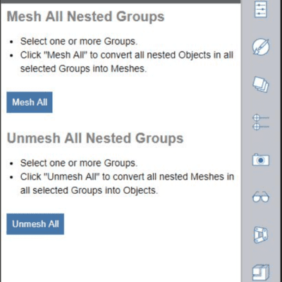
Step 2: Select the DWG and go to the Mesh + Unmesh All plug-in.
Step 3: Run the “Unmesh All Nested Groups” command. Everything should be individual lines now.
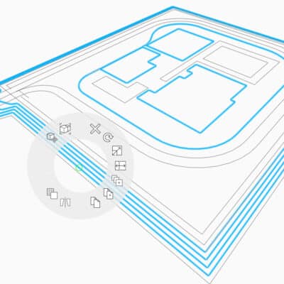
Step 4: Use the Loft tool to create the Site shape

Step 5: Select the first profile and use the “Next” arrow to select additional profiles. Once all profiles, or in this case the contour lines, are selected, hit the “Finish” checkmark.
Note: Be careful with the DWG file you have brought in. While the Loft tool does not need closed lines to work, the lines chosen do impact how the shape is formed. In this example, the DWG did not have a closed line at the top and so the Loft tool created a shape with a piece that was not ideal.

By closing the line, the Loft tool created a site that was more in line with what was expected.

Step 6: There will be no cap on the site after the Loft tool is complete.
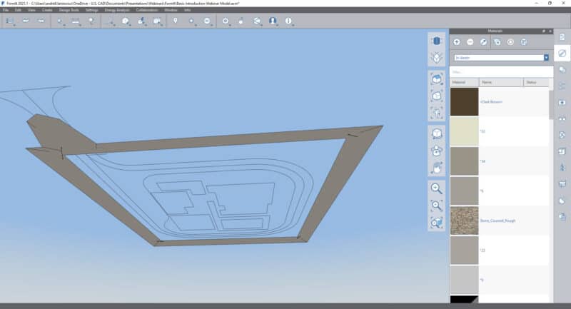
Use the Cover Tool. This is the end of what is required to create a nice site from an imported DWG file of contour lines.

Step 7: (Optional) Select the Lofted site shape and the Cover. Use the Merge Tool to combine them and remove most line work.

Note: We took it a step further and dragged a material onto the geometries to make them more visible and set some Visual Styles by turning on shadows and ambient shadows.

Working with Site contours in FormIt can be a simple task with the right tool! Being able to sculpt and sketch Sites in FormIt gives you the ability to make more detailed sites easier. It adds dimension to projects.
Additional Considerations when Working with DWGs
Should the DWG file being brought in not be in 3D (or rather, have changes in the Z axis), you can take the lines and manually raised them up. Depending on your site shape, you may only need to raise the Major lines and not the Minor. However, that will be up to each site and end goal to determine which way would work best.
Want to learn more about DWGs? Watch this webinar on Collaborating in AutoCAD with DWG Compare
Need another resource on FormIt? go HERE