The Building Blocks for Effective Corridor Assemblies in Civil 3D

The term corridor is pretty familiar to Civil 3D users—and its purpose is powerful. Basically, a corridor is a 3D representation of a path. A corridor can be any linear feature such as a road, harbor channel, railway line, or pipeline right of way, etc.
Every corridor combines an alignment, a profile, and assemblies to form a 3D representation. While the alignment and profile provide the horizontal and vertical aspects of the corridor, the assembly is a bit more complex.
Assemblies are a collection of subassembly objects that reflect the design cross-sections at various points along a corridor. On a road design, for instance, you will likely need multiple assemblies to reflect the changes in curbs, sidewalks, lanes, and shoulders along the path.
Assemblies are created and stored in the TOOLSPACE tab of Civil 3D. They can be shared from project to project, and inserted like Lego building blocks into a design to create a corridor.
To create an Assembly, go to the Home Tab and Click Assembly, Create Assembly. Assembly names are typically associated with the corridor (e.g., Collector-Full). Civil 3D provides a number of Assembly Types as well (e.g., Undivided Crowned Road, Railway). There are also Styles and Code Sets and Assembly Layer.
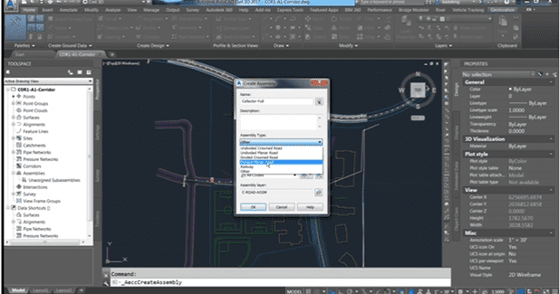
Once you click Ok, Civil 3D will ask where you would like to place the baseline for the assembly (pick a spot on your model) and a red center line and yellow point node will appear on the screen—this is your Baseline. The point node will connect with your profile or cross-section, so build from that point.
Note: Within Civil 3D, you can right-click on the left side to see all the standard pallets.
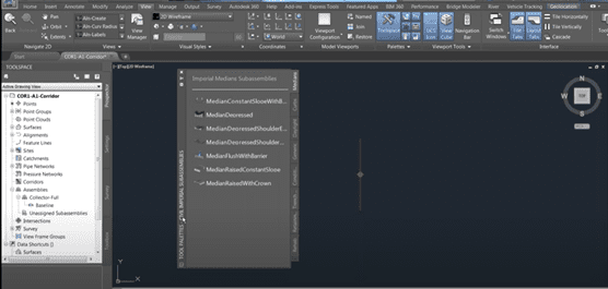
The Assembly Tab has all the tabs necessary to build your assembly including Medians, Curbs, Daylight, Trenching, etc. There are a number of pre-set assemblies as well.
Before you begin building your Assembly, verify your units! Check the Properties pallet on the right to make sure you have the right slope, width, depth parameters selected!
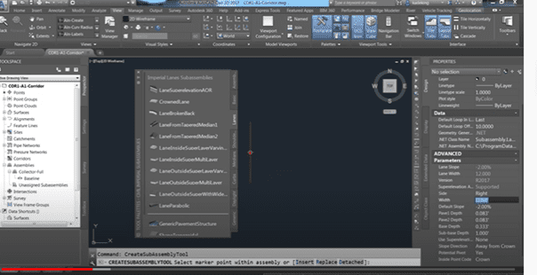
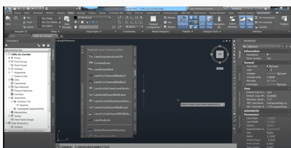
Now you’re ready to begin adding components to your assembly. As an example, select the LaneSuperelevationAOR (check your properties) and select the connection point. The lane subassembly will drop in at that point.
Now add a curb and gutter assembly. In this case, I selected the UrbanCurbGutterGeneral subassembly (again check the properties, especially parameters).

Now let’s mirror the subassembly to the left side. In this case, you’re going to use the Civil 3D Mirror Subassembly Command NOT the AutoCAD Mirror Command!
Once you’re done building the assembly, close the tool pallet. If you want to create a mirror of that assembly for the left side of your road, select all pieces of your subassembly, right-click, and select the Mirror Subassembly Command.

NOTE: This is the Civil 3D Mirror Subassembly Command NOT the AutoCAD mirror command.
Select the baseline point to use for the mirror and the program will flip all the pieces you selected to the other side. You can make changes to the left side as needed from the Properties tab.
Once you’ve created your assembly, you can right-click on the assembly name in the TOOLSPACE bar and look at the way the assembly is constructed under the Construction tab.

It’s a good idea to rename your elements at this time because it’s easier to locate assemblies in your model later on, especially when you’re trying to tie specific points on your corridor to a specific point in the assembly. The Construction tab is also a very easy way to edit properties.
Once you have your Assemblies created, it’s a simple matter to build corridors!
Next blog: Corridor Creation – How to combine profiles, assemblies, and alignments.